Abstract
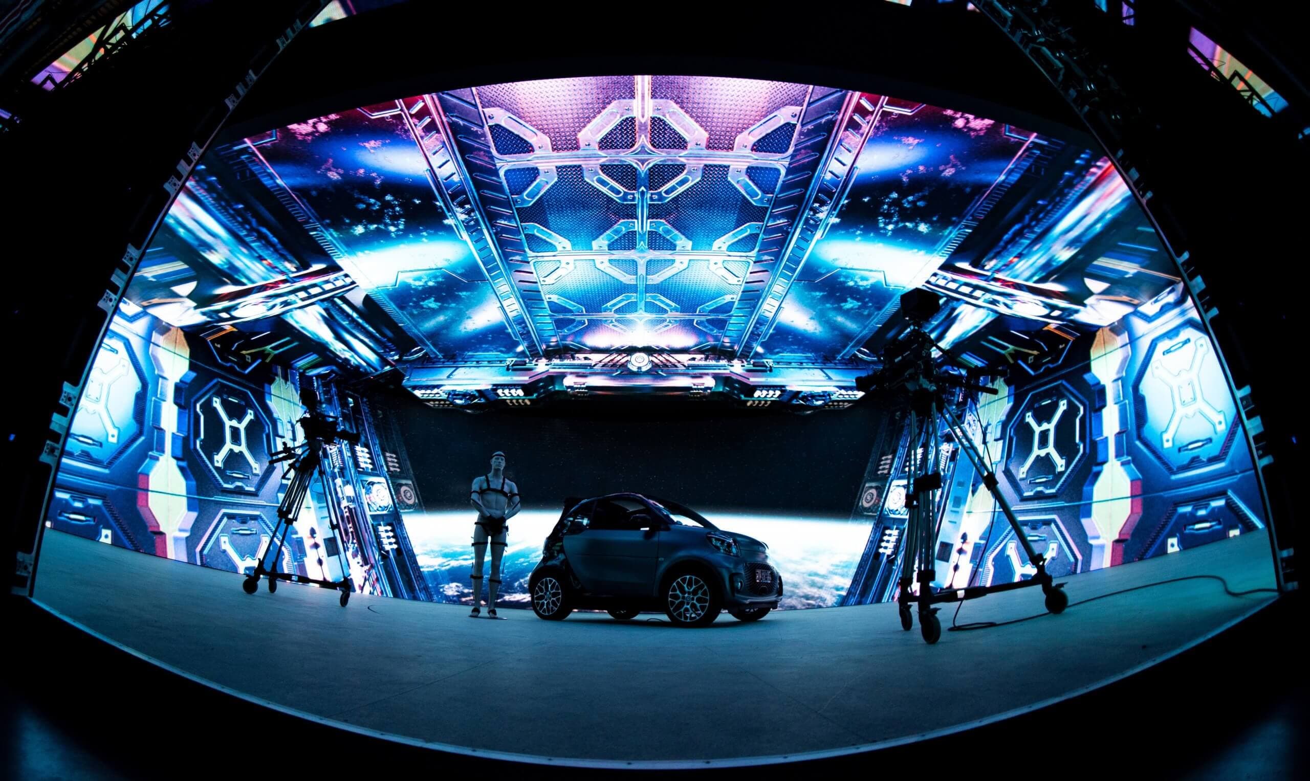
The increasing deployment of cylindrical and non-planar LED volumes in immersive visual simulation, virtual production (VP), and architectural displays introduces significant geometric perspective distortion. Standard Image Generators (IGs) render scenes under the assumption of planar projection surfaces. Consequently, when rendered perspective frustums are mapped onto curved physical LED structures, rectilinear features—such as horizons, architectural boundaries, and linear trajectories—suffer severe visual curvature relative to the observer's viewpoint. This white paper presents the methodology implemented in VIOSO LED Tools to resolve perspective distortion.
1. Geometric Perspective Distortion in Non-Planar Displays
Modern visual simulation environments and immersive display setups rely heavily on LED technology due to its superior luminance, high contrast ratio, and modular flexibility. However, the architectural transition from planar display arrays to curved, semi-immersive, or cylindrical LED volumes introduces fundamental optical challenges regarding perspective representation.
Standard rendering engines and Image Generators (IGs) generate synthetic imagery assuming an orthographic or standard planar perspective frustum projection onto a flat image plane. When this flat-projection image is mapped directly onto a physical display surface with non-zero curvature (such as a cylindrical or spherical LED wall), the spatial relationship between the rendered virtual camera and the physical observer's eye-point is compromised.
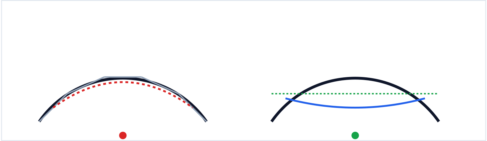
As illustrated in Figure 1, straight geometric entities in 3D world space (e.g., horizons, buildings, or road markings) undergo spatial transformation when rendered for a flat plane but displayed on a cylinder.
This discrepancy produces a severe optical artifact: straight horizontal structures appear convex or concave, depending on whether the observer position (Eye Point) is situated inside or outside the display's center of curvature. To achieve true visual fidelity, an intermediary spatial transformation must be applied to warp the image pre-rasterization or post-rendering.
2. Parametric Display Reconstruction via VIOSO LED Tools
To eliminate perspective distortion without requiring full screen calibration or complete re-rendering of the 3D scene, VIOSO LED Tools establishes a precise mathematical model of the physical LED display array. Unlike projection-based systems that rely purely on optical camera feedback, LED volumes consist of discrete, structurally fixed planar tiles arranged in 3D space.
2.1 Display surface and pixel space reconstruction
VIOSO LED Tools reconstructs the entire display surface parametrically by defining the exact structural building blocks of the LED wall:
- Physical Cabinet Dimensions: Precise width and height of individual LED cabinets (e.g., 200mm x 200mm).
- Pixel Pitch & Resolution: Discrete pixel density metrics defining the physical pitch in mm and module pixel resolution.
- Spatial Curvature & Vector Offsets: Angular displacement per tile column, or tessellated planar facet orientations in 3D cartesian coordinates.
2.2 Spatial Warping Algorithm
Once the mathematical surface mesh is reconstructed, VIOSO LED Tools calculates a transformation map. Given a defined eye point position, the software generates a per-pixel geometric warping lookup table (LUT). When applied to the output signal, the inverse spatial transformation cancels the physical curvature of the screen, guaranteeing that visuals for the observer at eye point perfectly replicate a linear 3D frustum.
3. Dynamic Real-Time Perspective Correction Pipeline
While static eye-point calibration is sufficient for fixed viewing locations, advanced simulation environments (motorsport driving simulators, vehicle test beds, and track-based virtual production stages) require dynamic adaptation as the observer or tracking camera moves in real-time relatively to screens.
3.1 Motion Tracking Integration & Dynamic Warping
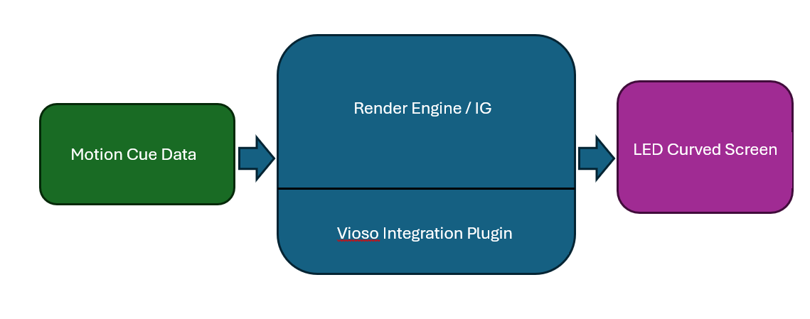
When the observer moves from one position to another, warping maps have to be different for each of those. VIOSO LED Tools overcomes this by offering dynamic correction through continuous spatial tracking integration.
3.2 VIOSO API & Plugin Integration
To eliminate latency overhead associated with external hardware warping boxes, VIOSO provides dedicated low-level integration plugins for major rendering engines. The integration operates as follows:
- Motion Cue Ingestion: The tracking system streams 6-DOF positional data of the observer's head (pilot, driver) or camera to the host application.
- Dynamic Frustum Recalculation: The VIOSO Integration Plugin receives the updated motion data and recomputes the projection frustum in sync with the engine frame render loop.
- GPU Shader Vertex/Fragment Warping: The calculated grid distortions are executed directly on the GPU within the engine's post-processing stack prior to frame-buffer swap.
This direct pipeline integration ensures sub-frame latency execution, keeping visual geometry aligned with physical space even during high-velocity motion trajectories.
4. Technical Performance Matrix
The operational capabilities of VIOSO LED Tools in comparison to generic flat-projection mapping and external hardware warping pipelines are summarized in Table 1.
| Parameter / Capability | Standard Flat Rendering | External Warping Hardware | VIOSO LED Tools Pipeline |
|---|---|---|---|
| Parametric Tile Geometry Reconstruction | None (Planar Output) | Manual Grid Adjustment | Fully Parametric (Module/Pitch Level) |
| Dynamic Eye-Point Recalculation | Unsupported | High Latency (> 2 frames) | Real-Time Direct GPU Shader Integration |
| Pipeline Latency Overhead | 0 ms | 16.6 ms – 33.3 ms (1-2 frames) | < 0.5 ms (Engine Native Execution) |
| Geometric Linearity Fidelity | Severe Perspective Curvature | Approximate Manual Alignment | Mathematically Perfect Point Alignment |
5. Summary & Conclusion
The proliferation of curved and non-planar LED volumes in professional visualization demands an advanced solution for perspective distortion. Standard rendering setups fail to account for display curvature, leading to severe visual distortion that compromises immersion and spatial realism.
Conclusion:VIOSO LED Tools provides an end-to-end, mathematically robust software framework specifically designed for non-planar display surfaces. By combining precise parametric hardware modeling with direct render-engine integration plugins for dynamic eye-point tracking, VIOSO LED Tools eliminates geometric perspective distortion with negligible latency. It stands as the definitive, industry-standard solution for advanced LED display calibration and real-time spatial correction.